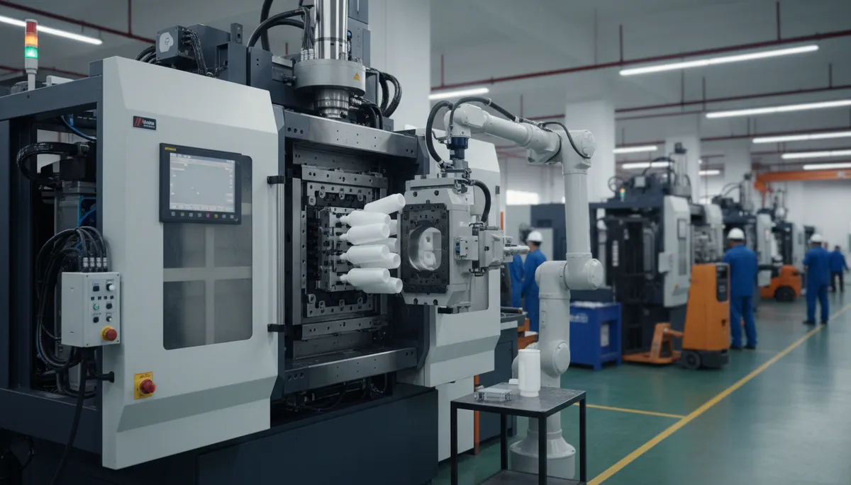
Precision engineering matters because an OEM mold has to control two different sources of error at the same time: the steel tool and the plastic material. A mold may be machined within ±0.08 mm, while resin shrinkage can add far more dimensional movement after molding. Protolabs, for example, publishes machining capability around ±0.003 in. (±0.076 mm), while molded-part variation also depends on resin, geometry, cooling, and processing conditions. A 100 mm dimension moving by only 0.2% changes by 0.20 mm. For OEM production, accurate steel is only useful when shrinkage, temperature, pressure, cooling, and inspection are controlled together.
The starting point is the part drawing, not the CNC machine. ISO 20457:2026 specifically treats plastic molded-part tolerances differently from metal tolerances because polymers experience larger dimensional changes from shrinkage, deformation, processing conditions, and non-uniform cooling. A supplier therefore needs to review datum structure, wall thickness, resin grade, draft, assembly fits, expected production quantity, measurement conditions, and dimensional requirements before cavity dimensions are released.
A tolerance such as ±0.05 mm can look simple on a drawing, but the manufacturing allowance becomes small once several sources of variation are added. If mold machining contributes ±0.02 mm, molding variation contributes another ±0.03 mm, and measurement repeatability adds ±0.01 mm, the process has little room for material-lot or temperature changes. Statistical capability should therefore be checked on production-representative parts rather than inferred from one first-off sample.
A dimension that passes on 5 hand-selected parts does not show whether a 50,000-part production run will remain inside the same limits.
Material behavior adds another layer. BASF's January 2025 data for Ultramid B3EG6, a PA6 containing 30% glass fiber, reports mold shrinkage of about 0.003 in./in. under the stated test conditions. A related BASF PA6-GF30 grade lists approximately 0.30% shrinkage parallel to flow and 0.75% normal to flow, a difference of 2.5 times between directions. Fiber orientation therefore needs to be considered when a housing has long locating dimensions or multiple mating points.
For a 120 mm feature, 0.30% contraction corresponds to 0.36 mm, while 0.75% corresponds to 0.90 mm. The 0.54 mm difference is much larger than the tolerance used on many clips, connector locations, bearing seats, or sealing features. A single shrinkage percentage applied uniformly to every axis can therefore produce a well-machined cavity and an incorrectly sized molded component.
Moisture can continue changing dimensions after the part leaves the mold. BASF lists equilibrium moisture absorption of roughly 1.9–2.3% at 23°C and 50% relative humidity for one PA6-GF30 grade, with water saturation around 6.3–6.9%. An OEM supplier working with polyamide has to define when dimensional inspection occurs and under what conditioning state; measuring immediately after molding and measuring after moisture equilibrium can produce different results.
That material behavior changes how steel dimensions should be finalized. Where practical, a supplier can leave selected features in a steel-safe condition during early trials so material is removed later rather than added by welding. Adding 0.05 mm by controlled machining is normally more predictable than repairing an oversize cavity surface after T0, especially where the repaired area forms a seal, textured surface, or visible Class-A face.
Machining capability still matters because the tool establishes the geometry from which every molding cycle starts. Published commercial injection-molding capability can be around ±0.003 in. or ±0.076 mm for mold machining, but that figure should not be confused with guaranteed molded-part tolerance. One manufacturing network, for comparison, states standard mold machining around ±0.125 mm and standard finished-part tolerance around ±0.250 mm, showing why an OEM buyer should request project-specific tolerances instead of assuming that “precision” has one industry-wide numerical definition.
| Engineering area | Example quantity to control | Production effect |
|---|---|---|
| Mold machining | ±0.02–0.08 mm on selected features | cavity location and fit |
| PA6-GF30 shrinkage | about 0.30–0.75% in published BASF data | final part dimensions |
| Mold temperature | about 80–90°C for the cited BASF grade | shrinkage and surface replication |
| Moisture at 23°C/50% RH | about 1.9–2.3% for the cited grade | post-mold dimensions |
| Multi-cavity balance | cavity-to-cavity measurements | weight and dimensional consistency |
Accurate inserts are only part of the stack. The core insert, cavity pocket, leader system, heel blocks, slides, lifters, wedges, parting surfaces, and mold base all contribute positional error. Four interfaces each shifted by 0.02 mm in an unfavorable direction can produce 0.08 mm of accumulated displacement even though every individual component appears reasonably accurate when inspected alone.
Parting surfaces make that accumulation visible. A small closure mismatch can show up as flash, witness marks, or a step along an exterior surface, while insufficient support can allow local mold deflection under cavity pressure. Precision work therefore includes fitting, spotting, guidance, shutoff geometry, preload, steel hardness, and support—not just cavity milling.
The next source of variation is temperature. Delrin's molding guidance recommends mold temperatures around 80–100°C for standard grades and notes that high-precision applications may require temperatures up to 120°C. It also explains that mold temperature affects crystallization, mold shrinkage, and later post-mold shrinkage. Running qualification at one mold temperature and mass production at another can therefore shift dimensions even when the steel remains unchanged.
Cooling-channel placement has to support the intended production cycle. If one side of a 2.5 mm wall cools faster than the other, the part can bend as the hotter region continues contracting after ejection. Increasing cooling time by 20% may reduce deformation during sampling, but an OEM factory running hundreds of thousands of cycles will usually expect the mold to meet dimensions at the agreed production cycle rather than at an artificially long trial setting.
A part should be qualified under a stable molding window, not under one machine setting chosen only because it produces a good measurement report.
Gate location then affects both filling and shrinkage. With fiber-reinforced resin, flow direction changes fiber orientation; with thicker sections, packing pressure may remain effective longer near the gate than at the end of fill. A difference of only 0.1% in local shrinkage equals 0.10 mm across a 100 mm span, enough to change alignment between screw bosses, clips, connector openings, or gasket surfaces.
Multi-cavity tooling makes the same problem easier to detect. An 8-cavity mold produces 8 parts during every cycle, so a 20-second cycle generates 1,440 parts per hour at theoretical continuous operation. If one cavity repeatedly produces a dimensional defect, 12.5% of every shot is affected. Checking only a combined sample can hide that pattern; cavity numbers should remain traceable through qualification whenever dimensions or part weight are sensitive.
For higher-volume work, inspection has to move beyond pass/fail measurements. Suppose a nominal 25.00 mm feature has limits of 24.90–25.10 mm, giving a total tolerance of 0.20 mm. A process centered at 25.00 mm with a standard deviation of 0.02 mm has a much different production margin from one with a 0.03 mm standard deviation, even though both may produce acceptable samples during an initial 30-piece study.
Process capability data also helps separate mold correction from process correction. If every cavity measures 0.08 mm undersize with tight repeatability, a steel adjustment may be appropriate. If dimensions move by 0.12 mm whenever packing pressure or coolant temperature changes, removing steel before stabilizing the process can create another problem. T0 and T1 reports should therefore include molding conditions beside dimensional results.
Tool life adds a longer time scale. A mold may pass qualification in 2026 and still be expected to make parts for 5, 8, or 10 years. Wear around gates, slide shutoffs, ejector bores, textured surfaces, and narrow core features gradually changes dimensions. Glass-filled materials can increase abrasive wear, so steel grade, hardness, coatings where appropriate, lubrication, spare components, and preventive-maintenance intervals should match the resin and expected shot count.
Replacement parts are another reason precision engineering matters. A worn insert produced after 700,000 cycles should ideally be manufactured from controlled CAD data, drawings, steel specifications, hardness requirements, and inspection references rather than being copied from a worn component. An OEM operating plants in the United States, Germany, Mexico, or the Czech Republic may not want to ship a complete multi-ton mold across borders whenever a small insert requires replacement.
The supplier also needs a controlled engineering-change process because OEM programs rarely remain unchanged for their entire life. A customer may move a clip by 0.30 mm, enlarge a connector opening by 0.50 mm, or change a resin grade after 18 months. Revision-controlled CAD, electrode records, inspection reports, mold-trial parameters, and modification history reduce the chance that a spare insert is manufactured to an obsolete geometry.
Working with an Injection molding production partner should therefore involve more than sending a STEP file and receiving molded samples. The supplier should be able to explain how shrinkage assumptions were selected, which dimensions were treated as steel-safe, how every cavity was measured, what temperature and pressure were used during qualification, and which dimensions require periodic checks after 100,000, 300,000, or 500,000 cycles.
Supplier evaluation can use numbers rather than broad claims. Ask for dimensional reports from at least 3 consecutive molding cycles across every cavity, the actual mold and melt temperatures used during approval, agreed critical-to-function dimensions, measurement equipment resolution, resin lot information, and mold-maintenance records. For a 16-cavity tool, 3 complete shots already provide 48 cavity-specific parts, which gives far more information than measuring five mixed samples.
A lower mold quotation does not automatically lower production cost. If a tool making 500,000 parts per year develops a 2% rejection rate, 10,000 molded components are lost annually before sorting, machine time, resin drying, labor, freight, and interrupted assembly are counted. Reducing that rejection level from 2% to 0.5% avoids 7,500 rejected pieces per 500,000 units.
Precision engineering is measured most usefully by repeatable production output, not by how accurate one newly machined cavity looks on an inspection machine. The OEM supplier has to keep tooling dimensions, resin shrinkage, moisture, temperature, cooling, gate behavior, cavity balance, measurement methods, maintenance, and future replacement components within an agreed manufacturing system over the full production program.